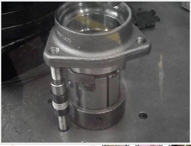
“Do I need to simply validate thread presence, overall functionality at some level or do I need/want conformance to traceable standards with real data as support?”
Here is a brief overview of the most common practices for automating thread evaluation available, categorized as non-contact and contact gauging, that can best solve your specific thread validation challenges.
Non-Contact Thread Checking Technologies – relative speed and throughput but at a cost/risk?
Proximity Sensors, Photo eyes, Fiber optics, Lasers – Cost effective Detect vs Measure
These technologies are all options employed to determine the presence of a thread. Their success or failure depend upon the quality of the environment, the set-up/fixturing, ability to dial in, adjust and “see” the threads. In these cases, quick and simple thread presence has to be enough to provide conformance to functional specifications for you or your customers. This will be lowest cost of entry for OD/ID thread checks from low to medium albeit with lowest assurances of thread validation.
Eddy current – open up and say ahh
Eddy current testing works by inserting a probe into a threaded hole. A coil in the probe is energized creating an electromagnetic field inducing eddy currents into your threaded metal component. This eddy-current result is compared against that of a known master component. When these results match/fall within your defined upper and lower control limits, the threads pass inspection. The key challenge here is one’s ability to establish these “control limits”, so that this solution will not fail conforming product or pass nonconforming product. While this technology is more forgiving to typical shop cutting fluids, vibration & temperatures, etc., thought and care must be given to eddy current probes as they can easily be damaged/broken and can be expensive to replace. If the probe finds an undersized hole or collides with a broken tap fragment, the internals can easily be damaged. This technology is sometimes protected using proximity sensors, photo eyes, fiber optics, and lasers as the first pass check to “save the probe”. While this inspection technique can be accomplished in ~1/2 seconds (this may be considered slow in the automation world), it functions as a better validation of thread presence and possibly depth with any hopes of capturing real pitch diameter off the table. This technology is not suited well for OD threads and requires a metallic (magnetic) component. Thick cast parts and blind holes can also be prohibitive.
Vision Systems – lights, camera, action
Vision solutions use sophisticated cameras to determine simple thread presence and can measure some attributes on OD threads (pitch, length). These systems can be very fast, reliable and effective. Parts can often be inspected on the fly, which can eliminate costly fixturing/set-up. While vision is usually the first method to be considered by end users, it is typically the last to be considered by the experienced machine builder/system integrator due to its highest hardware, implementation costs and potential limitations. Challenges with consistent lighting, vibration, optical distortion, dirt/oil/mist, can all take their toll on successful implementation; requiring preventive maintenance, continuous servicing/tweaking. The ability to validate internal threads is also limited typically to thread presence with these systems as well.
Contact Thread Checking Technologies – Automating the Functional Test
Rotary Contact Gauging – Get in, Get out, Good enough
Rotary contact gauging involves mechanically deploying a gauging member using air/stepper/servo motors, simple slip clutches, limit switches/proximity sensors (depth) and compliant tool holders (designed to prevent damage should an obstruction or other resistance be encountered). The appeal of rotary contact gaging is that it is a truly functional verification process. This method works well with either internal or external threads, and when the thread gauge members are selected properly, successful assembly of the gauged part (with its mating part) can be assured. While cycle rates can be under 1 second for this functional test, the key here is selection of the gauge member to assure a functional conforming thread (similarly to the Eddy current solution) but not fail conforming product or pass nonconforming product. Comparable in cost to some Eddy solutions, the need to incorporate this gauge member into your calibration system/preventive maintenance system is also paramount as these tend to be a wearing/perishable item.
SMAC Thread Checking Approach -When 100% Thread Verification is Required
SMAC’s thread checking systems function off the foundation of what has always worked well; the go thread gauge member (traceable back to National Standards) and advances it by enabling real time feedback of important thread attribute data. Using their 2-axis voice coil linear motor and low inertia custom wound servo motors (with encoder feedback) SMAC thread checking systems can:
- Soft-land (patented) on threads to prevent damage and assure easy gauge start
- Reverse to align & find first thread, (assure its position if important)
- Validate total turns, thread depth, running torque or an undersized pitch/depth condition
- Check for an on oversized pitch thread condition on the first 3 threads (traditional no-go gauge position), last 3 threads (linear clearance of the go gauge can be correlated directly to a measured pitch diameter dimension)
- Validate OD/ID threads, both through and blind
- Validate the presence of a spot-face or counterbore if present on part
- Send real thread data back to PLC (EIP/EtherCAT), PLC (Labview, 3rd party QA software, or serial)
- Use a master part to validate go gauge calibration/integrity as part of your quality assurance plan

