- Detailed instructions for Ford Galaxy (WRG) 2000–2006, 1.9 l 85 KW with engine code AUY, from model 2003 onwards
- Timing belt kits CT1028K3, CT1028WP2, and CT1028WP4
- ContiTech is demonstrating how mistakes can be prevented when replacing belts
When the timing belt is replaced, serious mistakes are often made. To ensure that the belts are replaced without any problems, ContiTech Power Transmission Group is providing fitters with detailed installation tips. Step by step, the ContiTech expert explains the proper procedure for replacing belts.
The manufacturer recommends that the timing belt be inspected and, if necessary, replaced every 90,000 km/five years on vehicles made from June 2003 onward and every 60,000 km/five years on vehicles made up to May 2003, including tensioner pulley and idler pulley. The manufacturer specifies a change interval for the tensioner pulley and idler pulley of every 180,000 km/ten years for vehicles made from June 2003 onward and every 60,000 km/five years for vehicles made up to May 2003.
The procedure takes 2.6 hours.
Tip: When the timing belt is changed, the tensioner pulley, the idler pulley, and the water pump should be replaced as well. In the event that the water pump subsequently fails, the entire process must be conducted again with new parts, as Ford has prohibited the reuse of used timing belts in this case. The water pump must therefore be replaced at the same time so as to prevent subsequent failures incurring unnecessary costs.
Fitters require the following special tools for the replacement:
The tools can also be found in ContiTech's Tool Box and Tool Box V01.
1. Camshaft locking tool OE (3359) (Tool Box V01-6)
2. Crank shaft locking tool OE (310-085) (Tool Box V01-20)
3. Arrester OE (205-072) (Tool Box -3)
4. Pin type face wrench OE (303-1053) (Tool Box V01-28)
5. Retaining tool, timing belt tensioner OE (303-1054) (Tool Box V01-25)
Preparatory work:
Identify the vehicle using the engine code.
Disconnect the vehicle's battery. Do not turn the crankshaft or camshaft when the timing belts have been removed. Turn the engine in the normal direction of rotation (clockwise), unless specified otherwise.
Turn the engine only at the crankshaft sprocket and not at other sprockets.
Comply with all vehicle manufacturers' tightening torques. Jack up the front of the vehicle and support it so that the front engine mount is unloaded.
Removal: disconnect the battery earth cable and remove the air filter housing, engine cover, intercooler line and bracket, lower engine cover, power steering line from the engine, assembly belt and assembly belt tensioner, upper and middle timing belt guards, crankshaft belt pulley, lower timing belt guard, and front engine mount (support the engine for this purpose).
Removing the camshaft belt:
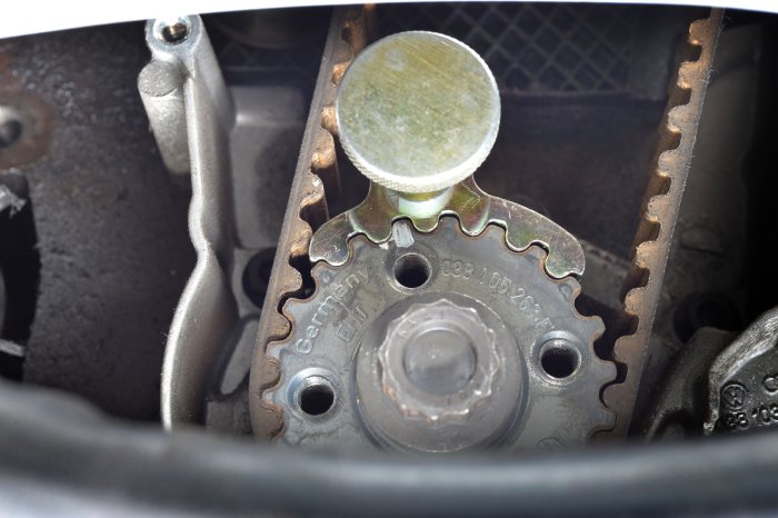
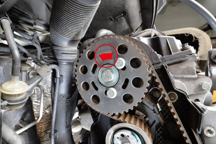
1. Set the control times at the TDC marking of cylinder 1. For this purpose, rotate the crank shaft in the direction of travel until the crank shaft marking is just before the 12 o'clock position (Fig. 1) and the "crown" of the camshaft sprocket is at the top (Fig. 2).
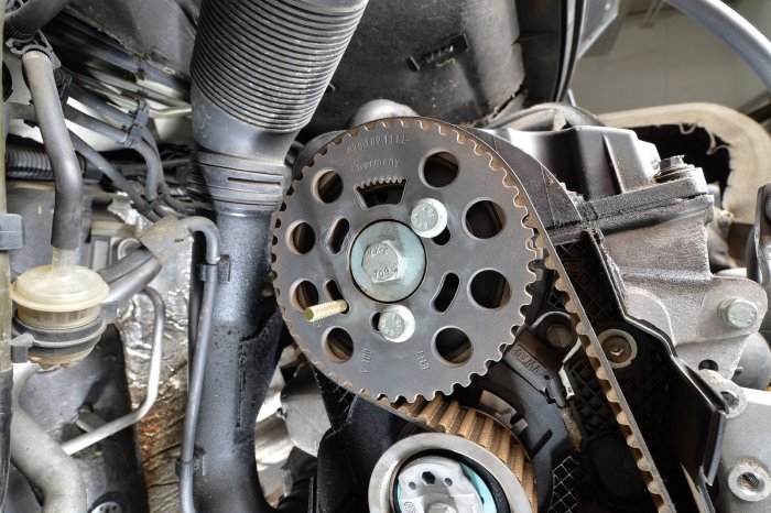
2. Mount the camshaft locking tool OE (303-376) on the camshaft (Fig. 3).
3. Insert the crank shaft locking tool OE (303-620) (Fig. 1). The marking on the tool OE (303-620) must align with the marking on the sprocket.
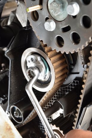
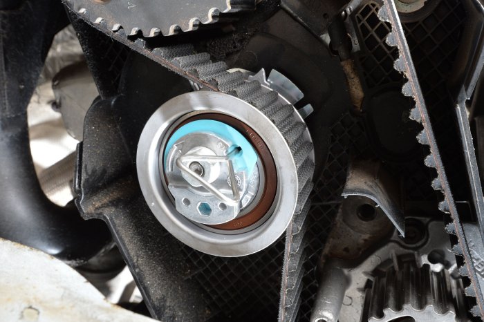
4. Loosen the screw of the tensioner pulley and relax the timing belt/tensioner pulley (Fig. 4).
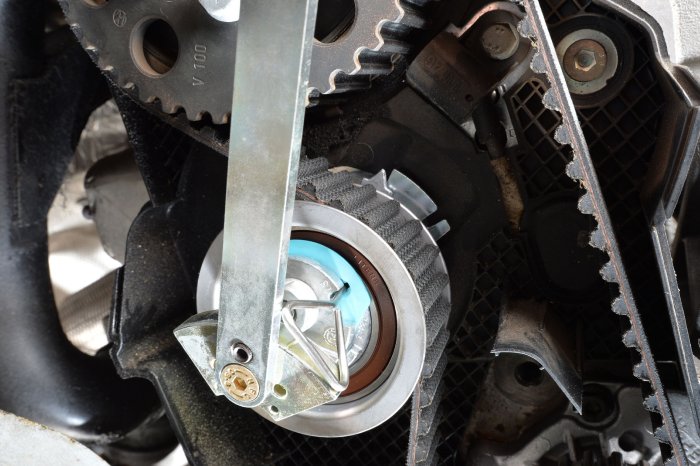
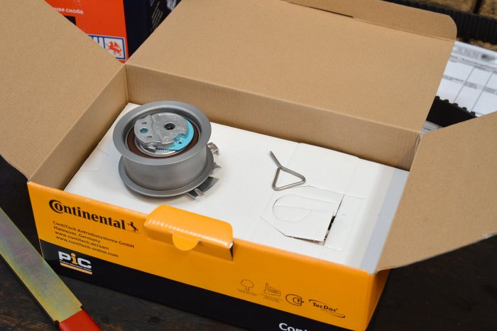
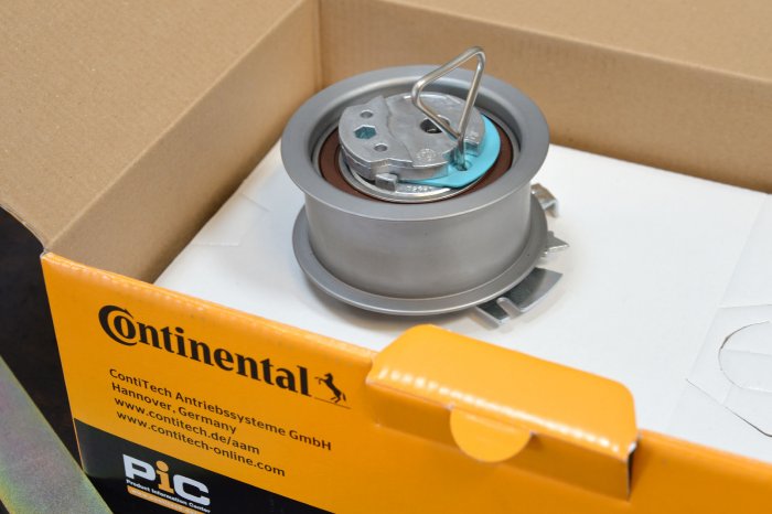
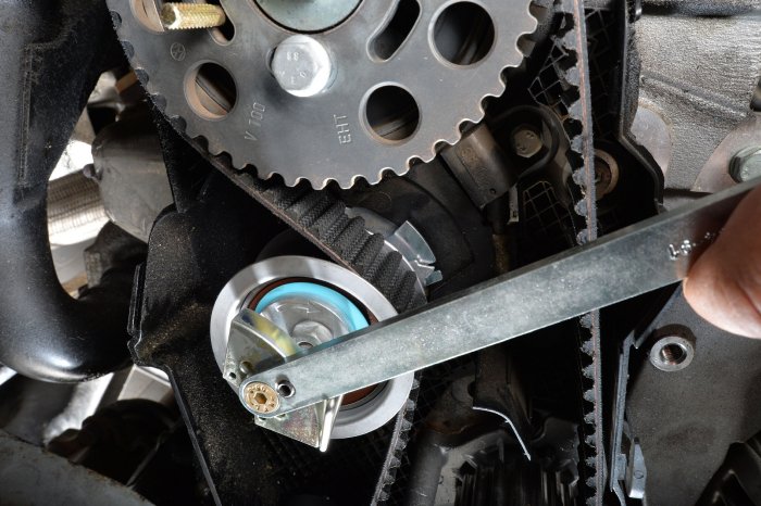
For this relaxation, rotate the eccentric of the tensioner pulley with the pin type face wrench OE (303-1053) anticlockwise until the retaining tool OE (303-1054) can be inserted in the tensioner pulley (Figs. 5, 6). In the new timing belt kit, the retaining tool sometimes comes loose in the packaging (Fig. 7). The retaining tool is required only to relax the timing belt. This is not a fully automated tensioning system! Using the pin type face wrench OE (303-1053), relax the eccentric in a clockwise direction. To do so, rotate the eccentric until stop and tighten the nut by hand.
5. The timing belt can now be removed.
Installing the camshaft belt:
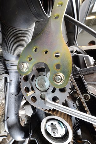
1. Loosen the screws on the camshaft sprockets. Please use the arrester OE (205-072) for this purpose (Fig. 8). Check the control times in the same way as for removal (points 1 to 3) and reset them if necessary. Set the loose camshaft sprocket in the center of the elongated holes.
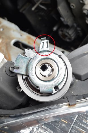
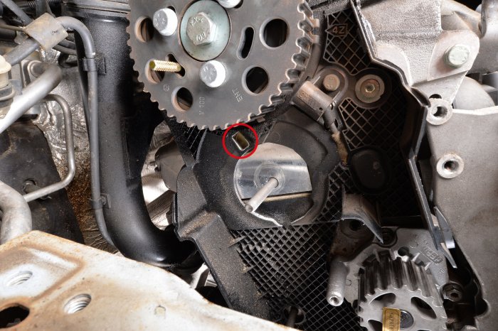
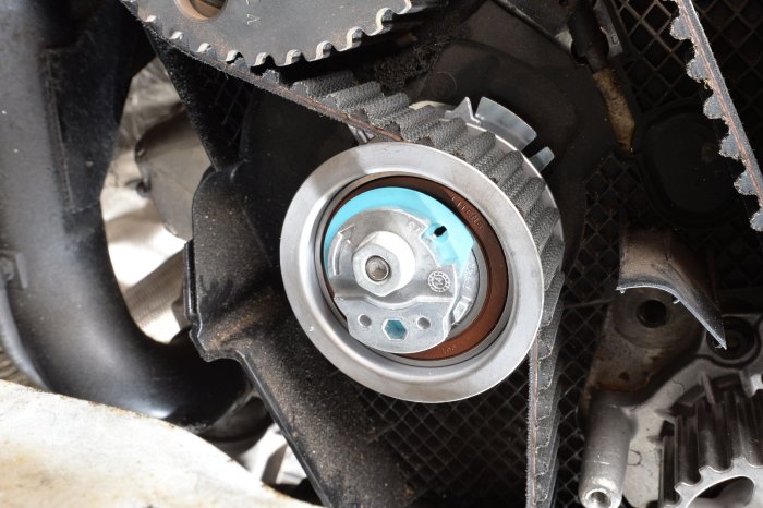
2. Install the new components. In doing so, ensure that for the tensioner pulley, the retaining bracket (Fig. 9) sits correctly in the fairing gap (Fig. 10). Install the tensioner pulley with tool 303-1054 inserted (Figs. 7, 11).
3. Lay the timing belt in an anticlockwise direction starting from the camshaft sprocket: camshaft sprocket, tensioner pulley, crank shaft sprocket, and finally water pump sprocket. Make sure that no kinks form on the timing belt during laying! The timing belt must be taut between the sprockets on the pull side!
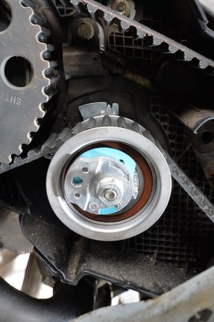
4. Rotate the tensioner pulley to the left (anticlockwise) with tool 303-1054 inserted until tool 303-1054 can be removed (Figs. 6, 12). Tighten the timing belt in a clockwise direction with the tensioner pulley and without locating pin 303-1054 inserted until the markings on the tensioner pulley align (Fig. 13, 14). Locate the eccentric of the tensioner pulley with pin type face wrench 303-1053 and tighten the nuts on the tensioner pulley with torque (20 Nm + 45 degrees).
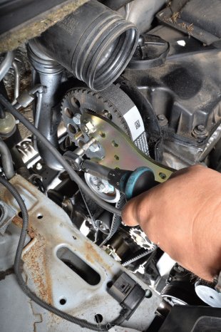
5. Remove the locking tools from the camshaft and crank shaft and tighten the screws on the camshafts with torque (25 Nm). Please use the arrester OE (205-072) for this purpose (Fig. 15).
6. Rotate the engine two turns in the direction of engine rotation. Position the engine at top dead center cylinder 1. Insert the camshaft and crank shaft locking tools. If the locking tool cannot be inserted, correct the control times. Check the timing belt tension again.
7. Remove the locking tools and install the components in reverse order of removal.
8. Installation: Upper timing belt guard (10 Nm), lower timing belt guard (7 Nm), crank shaft belt pulley (10 Nm + 90 degrees), assembly belt. Tighten the screws on the engine mount (3 x 60 Nm), the screws on the engine bracket (2 x 61 Nm), and the engine mount (1 x 54 Nm).
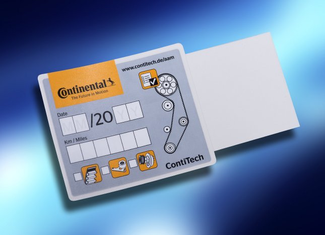
9. Record the replacement of the original ContiTech timing belt on the supplied sticker and affix it in the engine compartment (Fig. 16).
